
How to perform Tan Delta test / Dissipation Factor, step by step, with the ISA STS 5000 and how to interpret the values
Process of Tan Delta (Dissipation Factor or Power Factor) testing
Tan Delta test is an AC test in which we model the electrical insulation like a real capacitor. What we do is generate voltage and measure current caused by that voltage.
What interests us particularly is the phase angle between the voltage and the generated current. This phase shift tells us how much resistive current we have in the overall leakage current and that tells us how much our insulation is deteriorated or damaged.
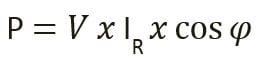
This is because resistive current is in phase with voltage and thus generates heat, which in turn deteriorates the insulation. The deteriorated insulation lets more resistive current to flow which further heats and deteriorates the insulation, which puts us in a vicious circle that could eventually end up as fault in the equipment.
How do we perform a tan delta test?
In a three-phase power transformer these are the steps to follow to perform the test:
- Disconnect the transformer from the grid
- Touch with a grounding rod all phases and all sides, to make sure there is not more energy in the PT
- Short Circuit all phases of primary, secondary side (see the picture below)
- Ground test set. If you use trolley, the test set and the trolley need to be grounded in the same point
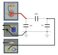
- If you use Isa STS 5000 + TD 50000 test set, first connect STS and TD – power and signal cable – and then turn on the test set
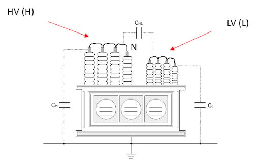
- Once turned on, connect the cables to the PT. Connect the HV generation to HV side of PT, and measurement cable (Input A) to LV side of PT
- This setup is used to measure CHL and CH
- On TDX 5000/STS 5000 choose PT, punch in the Nominal values and go to Test. The picture below shows how the firmware needs to be configured. Let us not forget that Tan Delta is also dependent on temperature, so for that we also use tab Temperature comp.
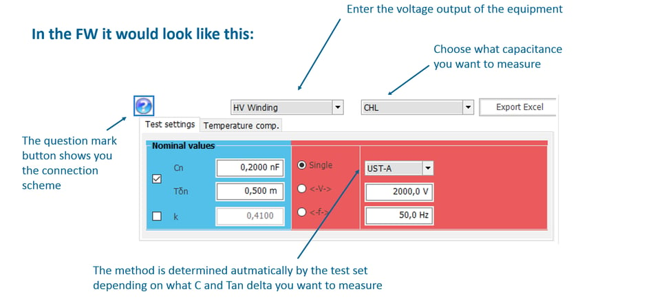
- Position correctly the cursor, add the test – then again position correctly the cursor and – make sure nobody is close to the PT - press START. Observe the lower left corner to see when the test is done. With this procedure you have measured CHL and the respective Tan Delta. So, insulation between HV and LV side
- Now on the display of the test set, choose CH, instead the CHL , add the test, correctly position cursor and make sure nobody is nearby. Press START again, when the test is done, check the result of CH and the respective Tan Delta. In this way we measured insulation between HV and ground
- Press the Emergency button as you approach the PT
- Now change the connection on the PT - the HV generation and connect it to the LV side and connect current measurement to the HV side of PT – basically generation and measurement change the positions. Configure the display so it looks like this:
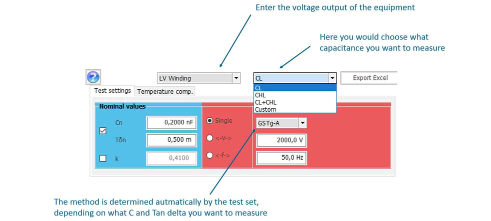
- Add the test, correctly position the cursor and make sure nobody is close by and press START. Look at the bottom left corner of the screen to see the steps that are being executed and when you see that the test is over - Check the result - With this procedure you have measured CL and the respective Tan Delta. So, insulation between LV side and the Ground. Press the Emergency button as you approach the PT
- Remove the Short Circuit of HV and LV side
- Connect the HV generation to the Bushing of HV Phase A and measurement to the test plug. Like in the picture below:
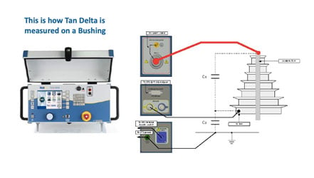
- Measure C1 and then C2 and be careful that when measuring C2 not to generate more than 1 kV
- Repeat the process for HV bushing Ph B and then Ph C
- If the LV side bushings have Tap Adapter – repeat that measurement on all phases of LV side
How do we Interpret the results?
When you finish, you will have these results
CH and tan (CH) also CL and tan (CL) and also CHL and tan (CHL)
For Bushings:
C1 and C2 - tan for (HV Ph A, Ph B and Ph C)
As you can see we have measured a lot of specific insulations, which is why this method has become a standard –because it can tell us, if the insulation is compromised, which exactly insulation is compromised – is it insulation between HV and LV or maybe insulation between LV and GND or maybe insulation on one of the bushings
Interpretation of the results:
All values should be less than 1 %
Also if you have previous values of and C, the change should not be too big
If this is not the fact, then Sweep of voltage (issue with PT body) or frequency (issues with bushing) should be done
More detailed table that helps us to interpret the results can be found below: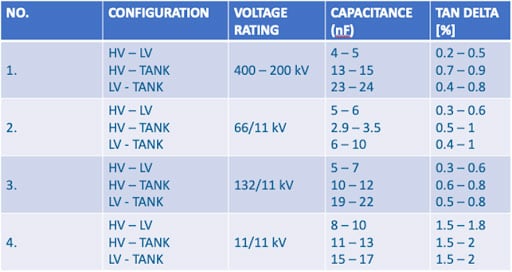
Read also: How to assess the condition of power transformer with ISA - ALTANOVA Group diagnostic equipment